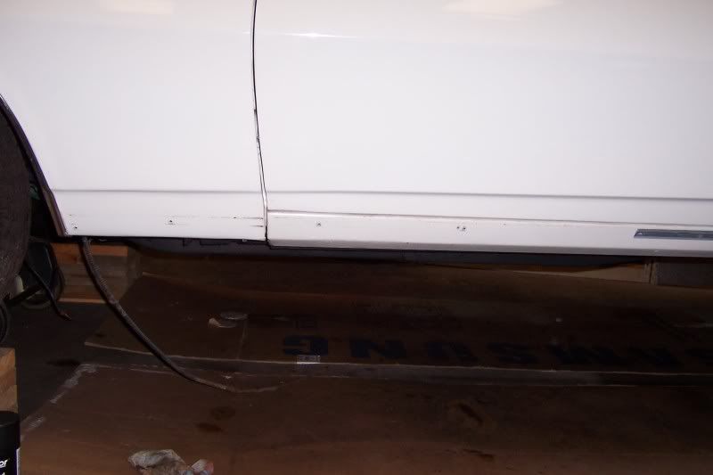
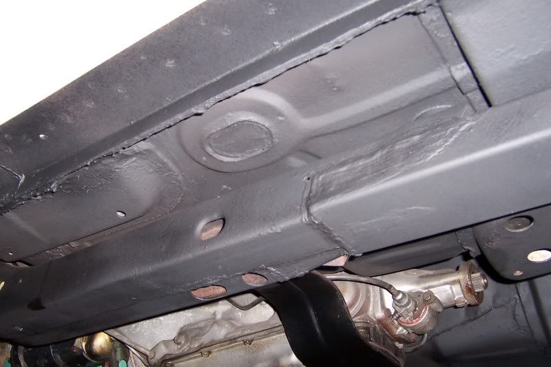
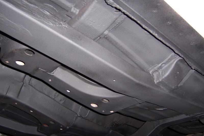
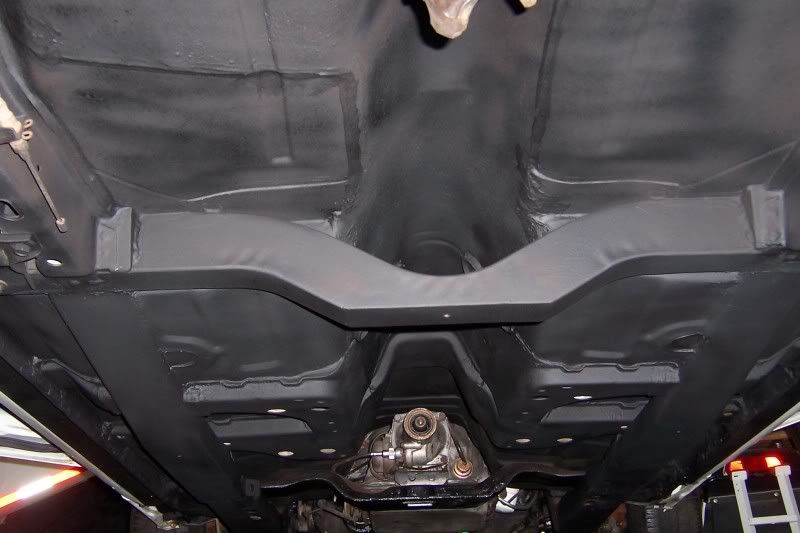
Thought I'd bump this since nobody has shared pics of weld-ins yet and I just finished mine. IMO weld-in connectors, fully integrated with the floor, is the only way to really do this. And none of these pre-fab weld-ins that duck under the floor bracing and stick too close to the ground! I've always hated the way bolt-in connectors, and most pre-fab weld-ins, kill ground clearance, and from a profile view they stick down just like old-fashioned traction bars and look goofy...they kinda uglify the profile of these cars. All my opinion of course...yours may vary and I totally respect that. Of course weld-ins that integrate with the floor will completely destroy originality, and that is a huge downside for many. But not for me. These are not rolling art...these are cars. Anywho...I'm just buttoning up chassis work on my 1968 Convertible. Decided to take a few pics before continuing with reassembly and bump this old topic to display what I did for chassis stiffening. Keep in mind this is all part of a comprehensive complete car rebuild...probably the 3rd or 4th resto done to this poor car over the decades and NOTHING remains original. PHS says it was born as a 350 convertible, and is now essentially a 400 convertible clone resto-mod, now with substantial permanent chassis stiffening. I put these connectors in along with new floors (lotsa patching at least), plus brand new rear frame rails (factory repops), but obviously the drop xmember is not remotely close to original, nor are the subframe connectors...those are both of my own engineering. I fabbed the subframe connectors myself out of 2 x 4 boxed steel. They intersect with and are welded to the factory convertible floor cross-bracing, and then protrude directly thru the floor at the rear passengers feet, where they tie into the drop crossmember. And to the backside of the drop crossmember the factory frame rails are directly attached. Hopefully the profile view shows how I've lost essentially ZERO ground clearance, which was my objective. And looking from the side of the car, you'd have to be familiar with the construction of these cars to even know the connectors are not factory...they're just straight extensions off the engine crossmember. So no casual passers-by will ever know there's something different from stock here...ya certainly can't say that about the chunky bolt-ins.
Of course bolt-ins can be installed in a day or less. This project too me MONTHS of labor LOL. So for ease of install...bolt-ins for sure! These integrated ones are NOT for the faint-of-heart when it comes to cutting a LOT of the car apart...
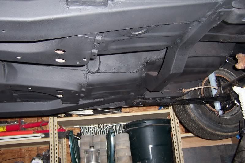
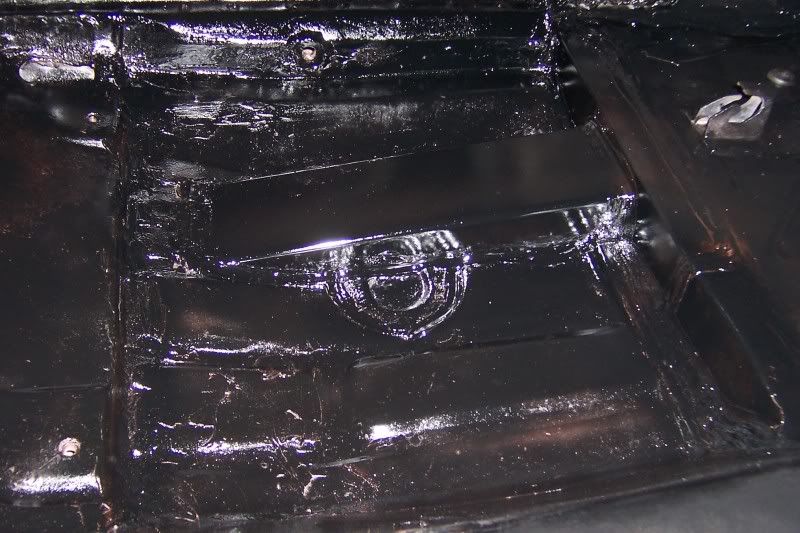
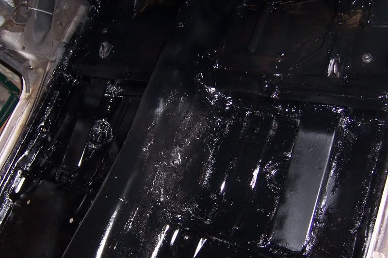
Sorry 'bout the photo of the interior...gloss black doesn't show real well in a flash photo of a bumpy seam sealed floor! But I think you get the idea. Obviously these require solid body mounts at the front engine/suspension crossemember...all rubber has been removed and replaced with aluminum units. This car is now STIFF! Creative carpet laying will be next for the back seat to try to hide the protrusion beams. Luckily I doubt this car will hardly ever see back seat passengers. Photos show the bolt-in convertible cross-brace removed...it will bolt into the factory position upon assembly of the rest of the car. Eventually this machine will see a bit of road-course track time, but just casual fun-stuff, no competitive racing. She'll be a street car...might even have it on the road this summer if I stay motivated and pressing forward.
Essentially I'm just sharing my solution to subframe connectors, for others who may be brainstorming ideas for your project: